

Overview
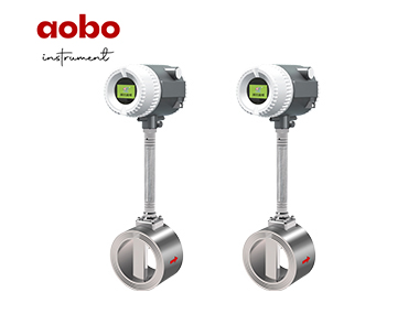
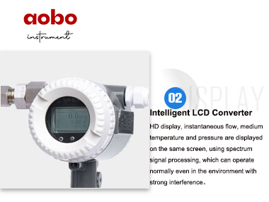
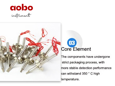
The vortex flowmeter is mainly used for the flow measurement of the pipeline medium fluid, such as gas, liquid, steam and other mediums, which is almost not affected by the fluid density, pressure, temperature and viscosity. The vortex flowmeter adopts a piezoelectric stress sensor, with high reliability, long service life and wide operating temperature range of (-20-350) ℃. With analog standard signal and digital pulse signal output, easy to use with computers and other digital systems, it is a relatively advanced and ideal measurement instrument.
Principle
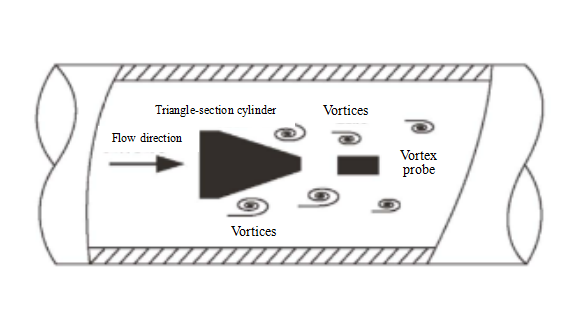
The vortex flowmeter is a fluid vibration instrument developed by the principle of "Karman vortex". A non-fluid vortex generator is placed in the fluid, which alternately separates on the sides of the vortex generator, releasing two columns of regular staggered arranged vortices.
Within a certain flow velocity range, the separation frequency of the vortices is proportional to the flow rate, which is detected by the piezoelectric ceramic detection element. It is transformed into alternating electric signals. After amplifying, filtering and shaping, it outputs a voltage pulse signal or (4-20) mA standard current signal proportional to the flow rate.
Feature
1. Wide measurement range;
2. High measurement accuracy;
3. Simple and firm structure, no moving parts, and long service life;
4. Simple maintenance, easy to install, small workload and low cost;
5. It has a wide range of applications. The flow of steam, gas and liquid can be measured;
6. It has a small pressure loss, high accuracy, good repeatability and good long-term working stability;
7. The output frequency signal is not affected by the fluid temperature, pressure, viscosity, density, etc.
Technical Parameter
Nominal general diameter: DN15-DN600
Nominal pressure: 1.6MPa, 2.5MPa, 4.0MPa
Measurement medium(s): liquid, gas, steam or other single phase or considered single phase mediums.
Medium temperature: (-20~350) ℃
Accuracy grade: grade 1.0 and grade 1.5.
Range degree: 1:10-1:15; intelligent type: above 1:15
Pressure loss factor: Cd=2.4
Output signal: square wave: Low level ≤ 0.5V, high level ≥ 5V, flow signal: (4-20) mA, HART protocol output
Power supply: DC 24V, DC 12V, DC 3.6V lithium battery
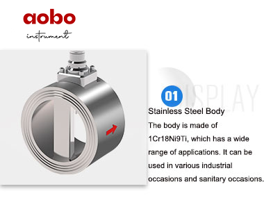
Case material: 1Cr18Ni9Ti, and other materials are required for the strong corrosion mediums.
Environmental conditions: (-40-55) ℃ [Field display type(-20~55) ℃], humidity of (5~90)%RH, atmospheric pressure of (8~106) KPa, explosion-proof type (-20~40) ℃
Protection grade: IP65
Explosion-proof grade: ExdIICT6Gb, explosion-proof number: SYEx19.12246
Installation
1.The upstream and downstream of the vortex flow sensor shall have a long enough straight pipe section (D is the sensor diameter) as required in the figure below.
Concentric contraction, full open valve Concentric pipe-expanding

Two 90-degree bends in different planes Two 90-degree bends in the same plane

A 90-degree bend Adjustment valve semi-open valve (not recommended)
2.When temperature pressure compensation is required, the pressure and temperature measurement points shall be set at the downstream end surface of the flow sensor (3-5) D and (6-8) D respectively, the pressure hole diameter (6-12) mm. The root of the pressure-taking short pipe is flush with the inner wall of the pipeline and shall not go deep into the inner wall of the pipeline. Insert the front end of the thermal resistance sheath into the center of the pipe as far as possible.
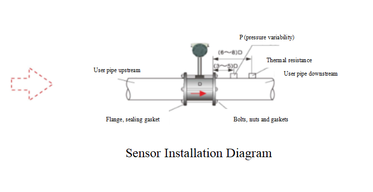
3. The inner diameter of upstream and downstream piping shall be the sensor diameter. If it is not, pipes that are slightly larger than the sensor diameter shall be used, The error shall be ≤ + 3%, and do not exceed 5mm; piping shall be concentric with the sensor, axiality<0.05D; gasket shall not protrude into the pipe and the inner diameter shall be larger than the sensor diameter (1-2) mm.
4. To avoid the influence of pipeline vibration, it should be considered to add fixed support about 2D upstream of the flowmeter or add elastic hose on the premise of satisfying the length requirement of straight pipe section before adding support.
5. The vortex flow sensor shall be installed in a safe place for installation, commissioning, overhaul and good environment. Enough operation space shall be left around. An operating platform shall be provided when installation at high altitude. Avoid installation in strong electromagnetic field, strong mechanical vibration environment and the environment of temperature and humidity not consistent with the service conditions.
6. The vortex flow sensor can be installed in the horizontal, vertical or inclined pipe, but the specific position shall be selected to ensure that the pipe is full and avoid the influence of bubbles when measuring liquid; the influence of liquid accumulation must be avoided when measuring gas (steam).

Liquid measurement
When measuring the liquid, the vortex flow sensor shall be installed at the lower part of the pipeline.

Gas measurement
When measuring gas (steam) flow, the vortex flow sensor shall be installed in the higher part of the pipeline.
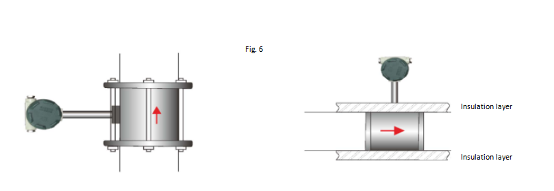
The vortex flow sensor is installed in the vertical pipeline. When measuring the gas (steam) flow, the flow direction of the medium is not limited; when measuring the liquid flow, the flow direction should be from bottom to top.
7.When the vortex flow sensor is installed in a horizontal pipeline, the meter head shall not be downward and shall be installed at an inclination of 45 degrees upward.
8. When installing the insert type vortex flow sensor, ensure that its axis coincides with the pipeline center line and it is perpendicular to the pipeline axis. The insertion depth meets the requirements and the flow direction is correct. The measuring head axis is parallel to the pipeline axis and the angle error is less than 7°. After the flow direction is adjusted, it should be locked to avoid rotation.
9. Before welding, the vortex flow sensor shall be removed. Welding with meter is prohibited; the flow sensor connecting rod cannot be insulated during pipeline insulation.
10. If necessary, the vortex flowmeter shall be reliably grounded, with a grounding resistance≤ 10Ω.
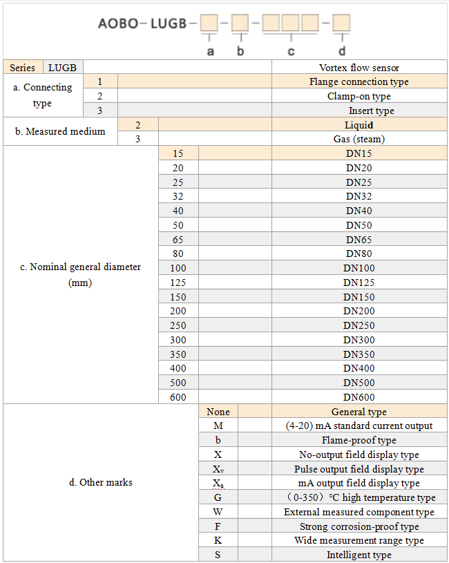
Type Selection
 Scan
QR code on WeChat Follow us

24-H hotline+86-536-7393118

Mobile phone+86-19953631088

Copyright (©) 2021 Weifang Aobo Instrument Technology Development Co.,Ltd Address:Building 4C, No. 8009, Minzhu street, Hanting District, Weifang City, Shandong Province (Hanting high tech Industrial Park) Record No:鲁ICP备2020035458号-5