

Overview
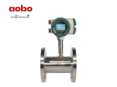
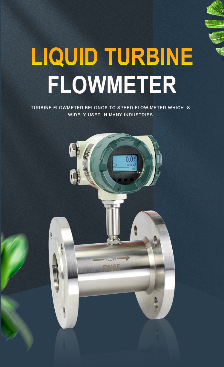
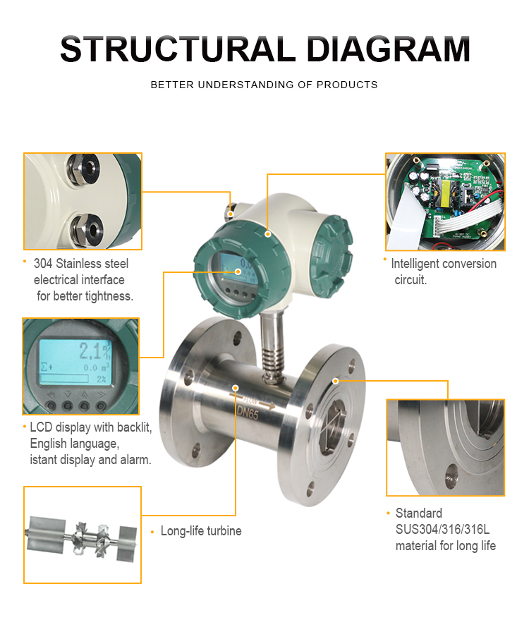
The liquid turbine flowmeter is a speed-type instrument, which has the advantages of simple structure, small volume, high accuracy, sensitive reaction, easy to install and maintain. It is used for measuring volume flow and accumulation of low viscosity, non-corrosive and clean liquids in closed pipes. If it is matched with the display instrument with special functions, it can also carry out quantitative control, over-limit alarm and so on. It is an ideal instrument for flow measurement and energy saving.
It can be widely used in petroleum, chemical industry, metallurgy, organic liquid,inorganic liquid, liquefied gas, urban gas pipe network, pharmaceutical, food, paper making and other industries.
Feature
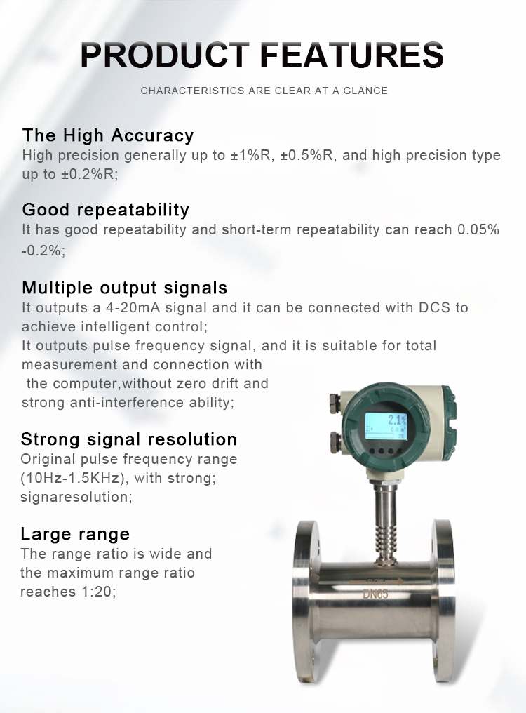
1. High precision, generally up to±1%R, ±0.5%R, and high precision type up to±0.2%R;
2. It has good repeatability and short-term repeatability can reach 0.05% -0.2%. It is due to good repeatability, normal calibration or online calibration can get extremely high accuracy, which is the preferred flowmeter in trade settlement;
3. It outputs a 4-20mA signal and it can be connected with DCS to achieve intelligent control;
4. It outputs pulse frequency signal, and it is suitable for total measurement and connection with the computer, without zero drift and strong anti-interference ability;
5. Original pulse frequency range (10Hz-1.5KHz), with strong signal resolution;
6. The range ratio is wide and the maximum range ratio reaches 1:20;
7. Compact and light structure, easy to install and maintain, with large circulation capacity;
8. It is applicable to high pressure measurement and we do not have to open a hole on the sensor meter body. It is easy to make high pressure type instruments.
Principle
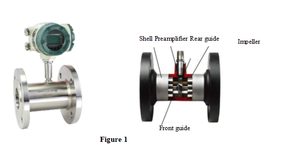
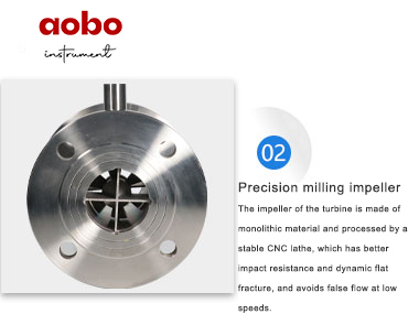
Fig.1 shows a brief diagram of the liquid turbine flowsensor structure. It is shown from the figure, When the measured liquid flows through the sensor, under the action of the fluid, the impeller rotates under force, and its speed is proportional to the average flow velocity of the pipeline. The rotation of the impeller periodically changes the magnetoresistance value of the magnetoelectric converter. The magnetic flux in the detection coil changes periodically, producing a periodic induction potential, that is, the electric pulse signal and it is sent to the display instrument after amplification.
Parameter
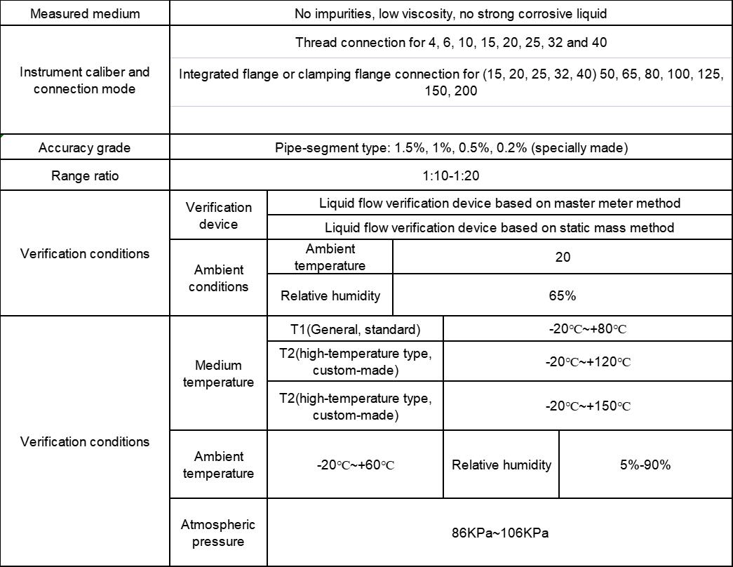
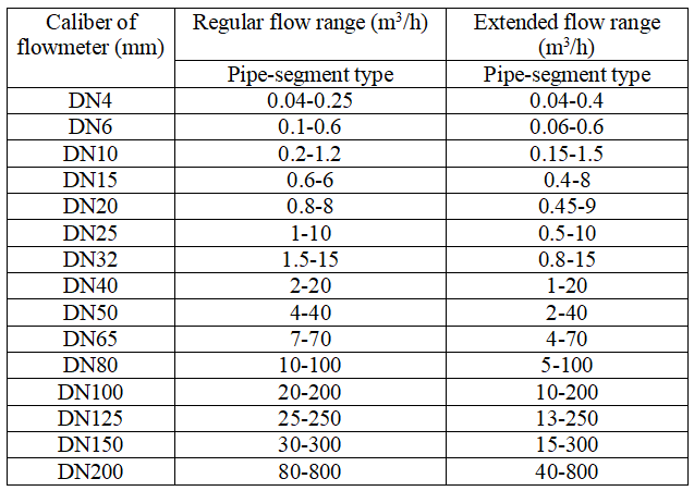
Caliber-Flow
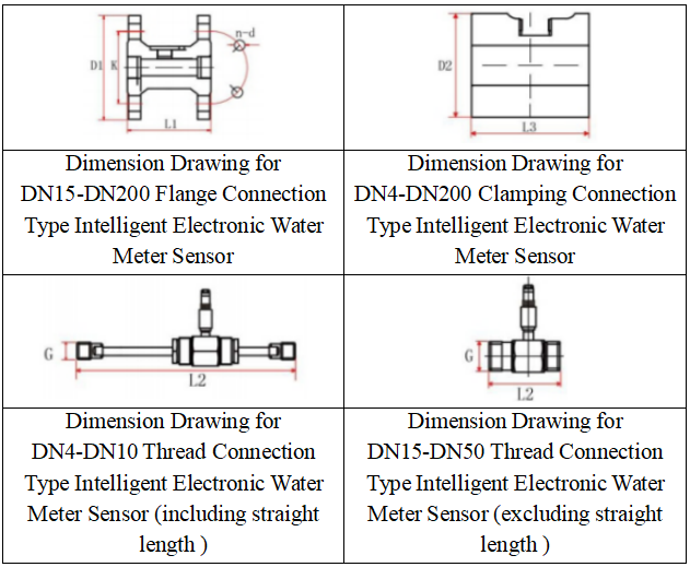
Installation
Installation mode of pipe-segment type liquid turbine flowmeter
Installation conditions and location
(1) The pipe must be fully filled with liquid. It is important to keep the pipe completely full of liquid at any time, otherwise the flow display will be affected and it may cause measurement errors.
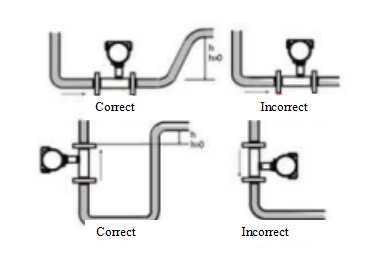
(2) Avoid air bubbles. If there are air bubbles entering the measurement pipe, the flow display may be affected and it may lead to the measurement errors.
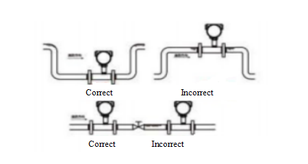
Installation Site and Requirements

(1) Sensors shall be installed in a place for easy maintenance, no vibration, no strong electromagnetic interference and thermal radiation.
(2) Horizontal sensor installation requires that the pipeline shall not be visually tilted (generally within 5°), and the vertical deviation of vertical installation sensor pipeline shall be less than 5°. In places that cannot stop flow, bypass pipe and reliable stop valve should be installed (see above) to ensure no leakage.
(3) Connect a section of short pipe to replace the sensor at the position of the newly laid pipe to install the sensor. After the "pigging" is completed, confirm that the pipeline is cleaned and then formally connect the sensor.
(4) If the fluid contains impurities, the filter shall be installed upstream of the sensor and the pipe should be regularly cleaned and discharged precipitated impurities; if the measured liquid contains gas, the silencer shall be installed on the upstream side of the sensor. The drain outlets and air outlets of filters and silencers shall lead to safe places.
(5) When the sensor is installed outdoors, measures should be taken to prevent direct sunlight and prevent rain.
3. Intelligent liquid turbine flowmeter for straight length is sensitive to flow velocity distribution distortion and rotation flow in the pipeline, and the liquid flowing into the sensor shall be the fully developed turbulence. Therefore, it is required to provide the necessary straight length or rectifier according to the baffle type in the upstream side of sensor, and the straight length for inlet and outlet sections are required.
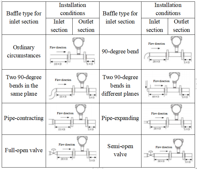
Examples for installation dimensions
The dimensions shown in Table 7 are the minimum installation length of straight length to ensure accuracy. If the length of straight length is doubled, the accuracy can be improved.
Upstream: the allowable minimum straight length is at least 10 times of the pipe diameter.
For example, the ABLWGY-50, upstream straight length is at least 500mm and the desired upstream straight section length shall be 1,000mm.
Downstream: the minimum allowable straight length is at least 5 times of the pipe diameter.
For example, the ABLWGY-50, downstream straight length is at least 250mm. The desired length of the downstream straight length shall be 500mm.
Product Details

 Scan
QR code on WeChat Follow us

24-H hotline+86-536-7393118

Mobile phone+86-19953631088

Copyright (©) 2021 Weifang Aobo Instrument Technology Development Co.,Ltd Address:Building 4C, No. 8009, Minzhu street, Hanting District, Weifang City, Shandong Province (Hanting high tech Industrial Park) Record No:鲁ICP备2020035458号-5