

Overview
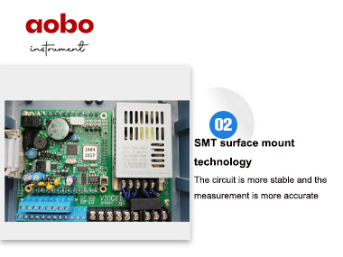
Up to date, the high fuction,low price,good reliability,power function,new series products enhanced greatly in the aspects of measurement,accuracy,measurement stability,communication protocol,easy to use etc. easy and reliable production line,good conformity of the products that gurantees each instrument reach the best function before leaving factory.
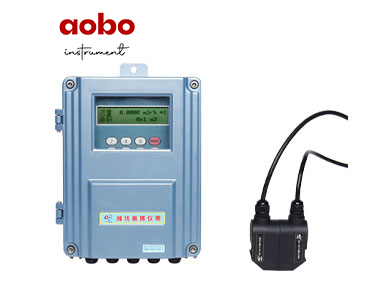
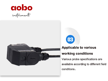
The main board is suitable for any kinds of transducers,including clamp-on type,insertion type, π in-line type,standard in-line type and same kinds of transducers from other manufacturers.the pipe parameters and calibration parameters of water meter and in-line pipe are input by manufacter,users do not need to input any parameter,only need to connect with flowmeter to work.
Applied to on-line measure and system monitor for nearly all liquids from petrol chemical,metallurgy,electric power plant,irrigation,city water company,energy monitor fields,realize the functions of measuring and checking of flow velocity,flow rate,accumulation and heat quantity of different liquids,and flow rate on/off,liquids distinguish.
Principle
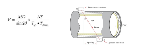
Remarks:
θ The angle between the ultrasonic beam and the flow
M Transit times of the ultrasonic beam D The internal diameter of the pipe Tup Transit time in the forward direction Tdown Transit time in the reverse direction ΔT=Tup –Tdown
F=900×π×D2×V
F is instant flow rate(unit:m³/hour) D is inside pipe diameter(unit:m) V is flow velocity(unit:m/s)
Parameter
1. Power supply:AC 85—264V or isolation DC 8-36VDC
2. Repeatability:better than 0.2%.
3. Accuracy:better than 1%
4. Signal output :one channel standard isolation RS485 output;
One channel isolation 4-20mA or 0-20mA active output;
One channel OCT output(programmed between the pulse width(6-1000ms),default before leaving factory (200ms));
One channel isolation relay output,with positive,negative,net accumulation pulses and different alarm signals.
5. Signal input: two channel three wire system PT100 platinum resistor input loop,to make heat meter has the function of displaying heat quantity;
Three channel 4-20mA input optional,accuracy:0.1%,has the ability to input the signals of pressure, liquid level, temperature and so on.
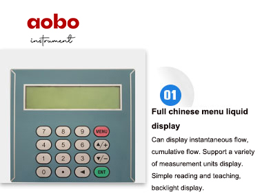
6. Display:2*20 backlit LCD(Chinese and English optional)
7. Operating:4*4 tactile keypad
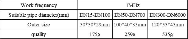
8. Protection level:mainframe:IP65, transducer:IP:68
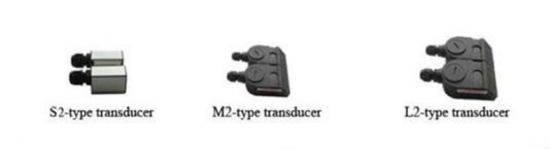
9. Transducer: clamp-on type,insertion type,in-line type.
Other functions:automatic memory the positive,negative,net totaliser flow rate and heat quantity of the last 512 days,128 months,10years.
Automatic memory the time of power on/off and flow rate of the last 30 times, realize to replenish by hand or automatically,read the datas through Modbus communication protocol.
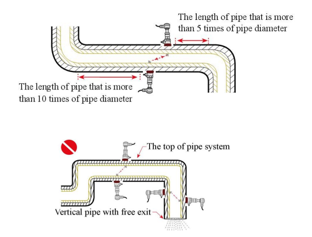
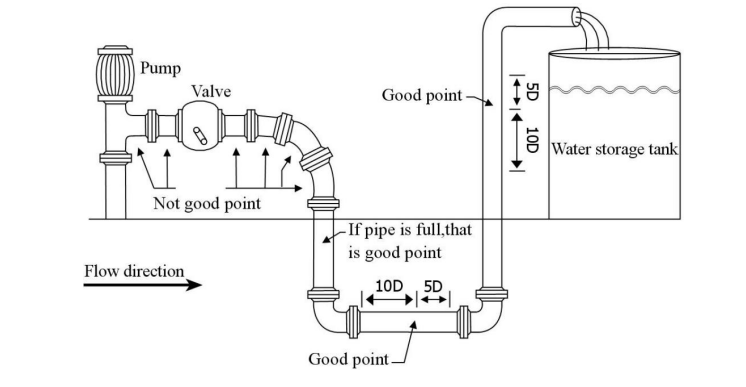
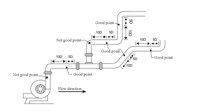
2. Upstream transducer should be installed at the place where the upstream length of the straight pipe is at least 10D and the downstream length is at least 5D where install the downstream transducer,so the pipe length should be straight without any valve,pump,angle head, D stands for pipe ouside diameter. The installation point should stay away from valves,pump,high pressure current,transformers interference source etc.
Avoid to install on the highest point of pipe system or vertical pipe with free exit(flow down)
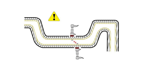
For the opened pipe or half full pipe,the transducers should be installed on U pipe.
The temperature and pressure on the installation point should be within the work ability of the transducers.
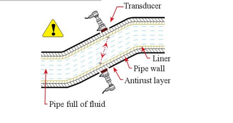
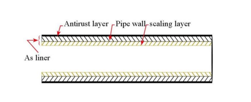
Pay more attention to the pipe scaling in inner pipe wall,do best to choose the pipe without scaling to install,if it is impossible ,then consider the scaling as liner to achieve better accuracy.
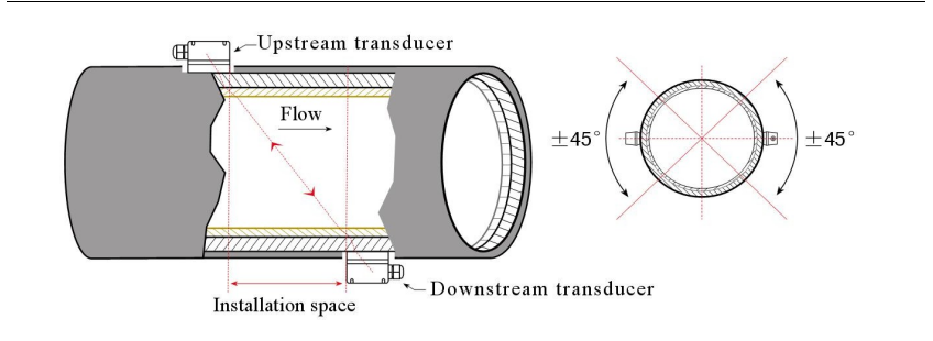
The two transducers must be installed in horizontal direction to pipe axis plane,within ±45°of axis line horizontal plane, to prevent bubbles or not full in upper pipe or sediment in down side of pipe to influence transducer measurement normaly.if there is space limit of installation that could not install horizontal symmetry,then install the transducers vertically or dip angle under the condition of no bubbles in upper parts of pipe.
Clamp on type transducer installation method
Before installation,choose density pipe to install transducers,and clean the installation area,clear away rust,paint,anti-rust layer,it is the best to use angle grinder to polish,use cleaning cloth with alcohol or acetone to clear oil and dust,coat enough couplant around the center of installation area,attach the transducers on the pipe and fix it without air bubbles or sand between transducers and pipe wall.
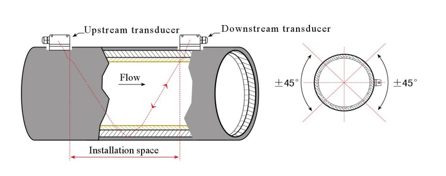
When the pipe diameter is wide,or there are suspended matters in fluid,too thick scaling or liner inside pipe inner wall,that can make the flow meter can not work normaly and signal poor by using V method installation,so need to use Z method to install,its features are direct transfering without reflection(called sigle sound path),little signal attenuation.
Attention:1,when installation,it is a must to clear the pipe area where to install transducers,showing metal color
2,shield line of ultrasonic signal cable can not be connected,but not short circuit with positive and negative pole(red and black line)
3,after transducers are connected with circuits,must apply enough sealant to prevent water in. 4,after covering the transducers,must screw and lock tightly the hole for shield line of transducers to
prevent water in.
5,use strap(stainless steel band) to fix on the center part of transducers,to make it weighted uniform,no moving.
6,apply enough couplant around the area ,so that transducers touch pipe to prevent air,sands,rust in,that influence the beam transfering.
 Scan
QR code on WeChat Follow us
Scan
QR code on WeChat Follow us

24-H hotline+86-536-7393118

Mobile phone+86-19953631088

Copyright (©) 2021 Weifang Aobo Instrument Technology Development Co.,Ltd Address:Building 4C, No. 8009, Minzhu street, Hanting District, Weifang City, Shandong Province (Hanting high tech Industrial Park) Record No:鲁ICP备2020035458号-5